
Physical Computing, 2021
EyeballBot
An interactive piece created for play. Make the bot move using a flashlight: the eye will follow the light.


How it Works:
EyeballBot consists of a 3D printed eyeball, mounted on an internal support, and connected to two servo motors. The user controls the eyeball using a flashlight. Integrated in to the pupil are three photosensitive sensors. Using input from these sensors the Arduino program triangulates the input, and tells the motors the position the eyeball should move to.
Design Process:
Task: Create an interactive sculpture using two servo motors with PID control, and one sensor
Project Duration: 2 weeks
Project Criteria: Must demonstrates controlled & designed motion, Motors must work together to control in coupled motion & must include one additional integrated sensor
Ideation: We began with a broad brainstorm that surveyed the sensors we had access to and interactions found interesting. During our second brainstorm, I pitched creating a large realistic looking eyeball that would move via light sensor input using two servo motors. We settled on this and ideated around a mechanism for controlling the eyeball's movement.
Research: We briefly surveyed various mechanisms used by animatronic eyes, and looked at similar work using Arduino


Design Criteria: (we determined four standards to measure and enable our success)
Eyeball must to be light, smooth and spherical - to create smooth gliding motion and minimize friction
Eyeball support should allow for free motion and a box unit will contain the whole mechanism
Eyeball should look realistic, and feel real and look finished
Eyeball must to move with user input - either from a light or sound sensor
Eyeball Prototypes: I created multiple material drafts for the eyeball using plaster and 3D printing.

The plaster experiments failed because they were too fragile and non spherical, so I pivoted to 3D printing. This option created an eyeball that would be heavier, but would be sturdy and spherical.
Box Construction: We calculated the space required for the horns’ movement, to determining the size of the eyeball housing. After finding the space needed between the horns, eyes, and the back of the box, our dimensions were: 10.5 x 11 x 15 in.
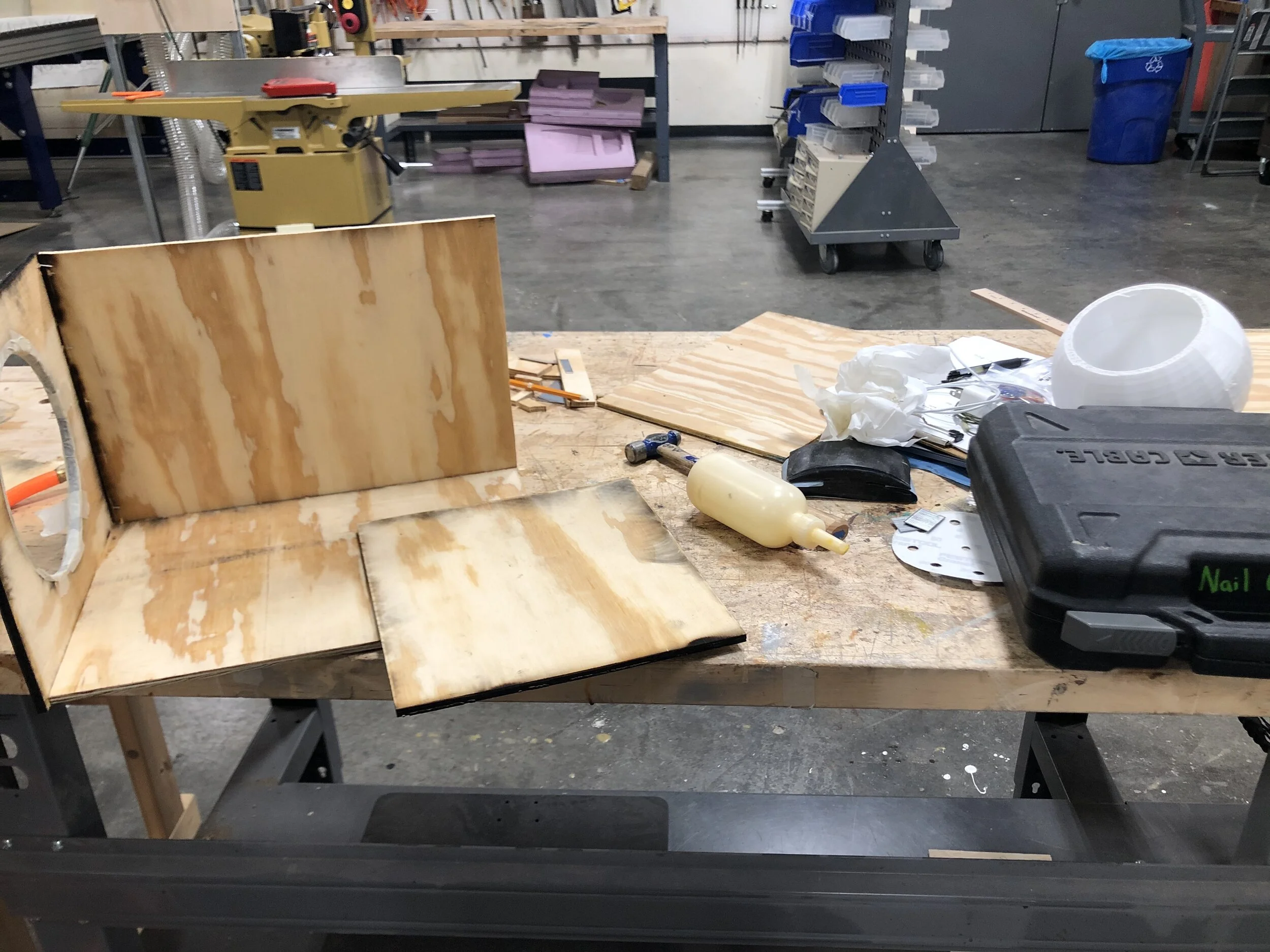
Box was assembled using the laser cutter, plywood, nail gun, and wood glue
Eyeball Support Structure: During the build we created two versions of the eyeball support structure.
Version 1: External Support Structure, made on the fly, was not symmetrical, and cause eye to dislocate in the socket.
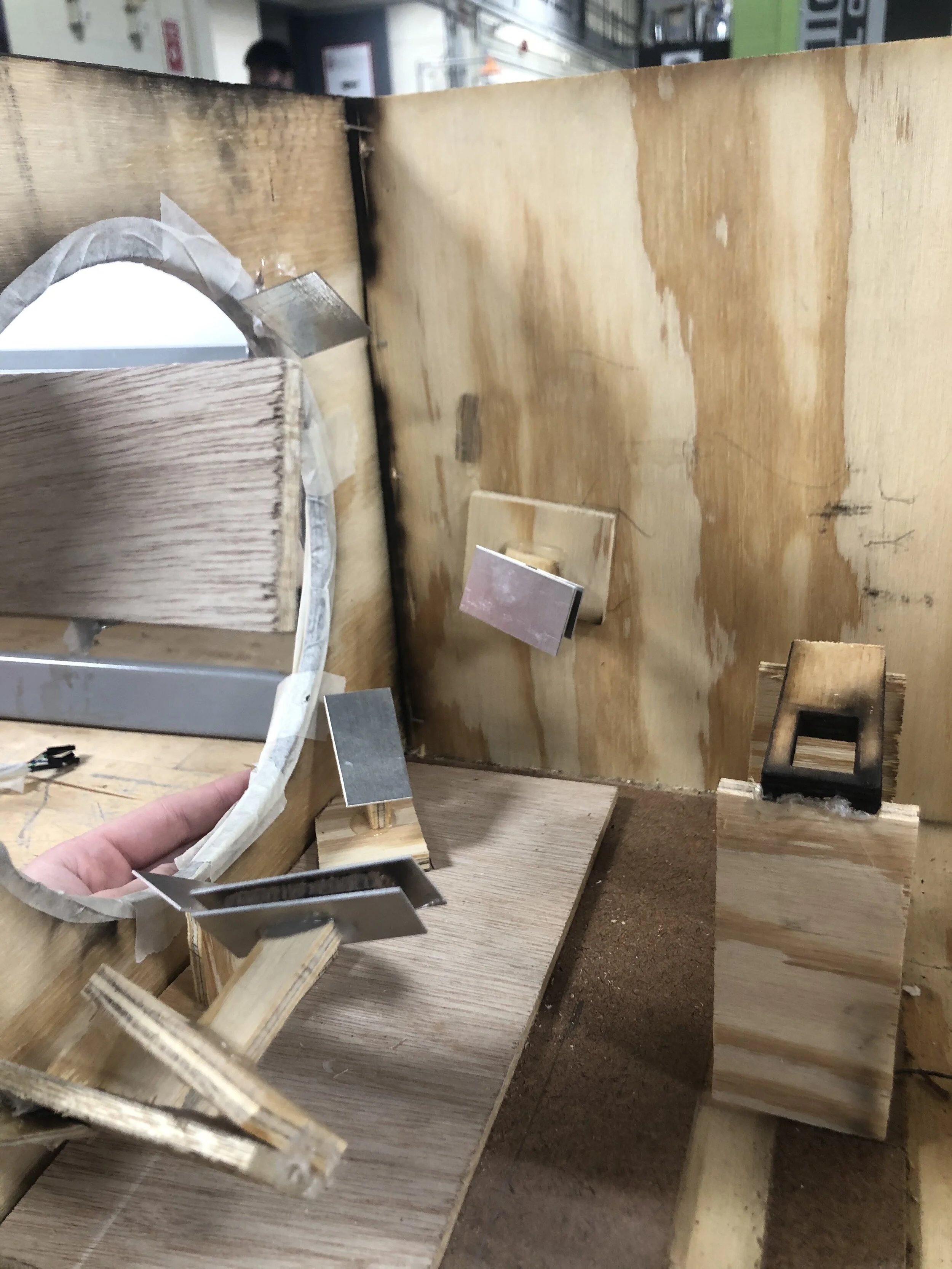
External Supports
External Support Structure with Eyeball
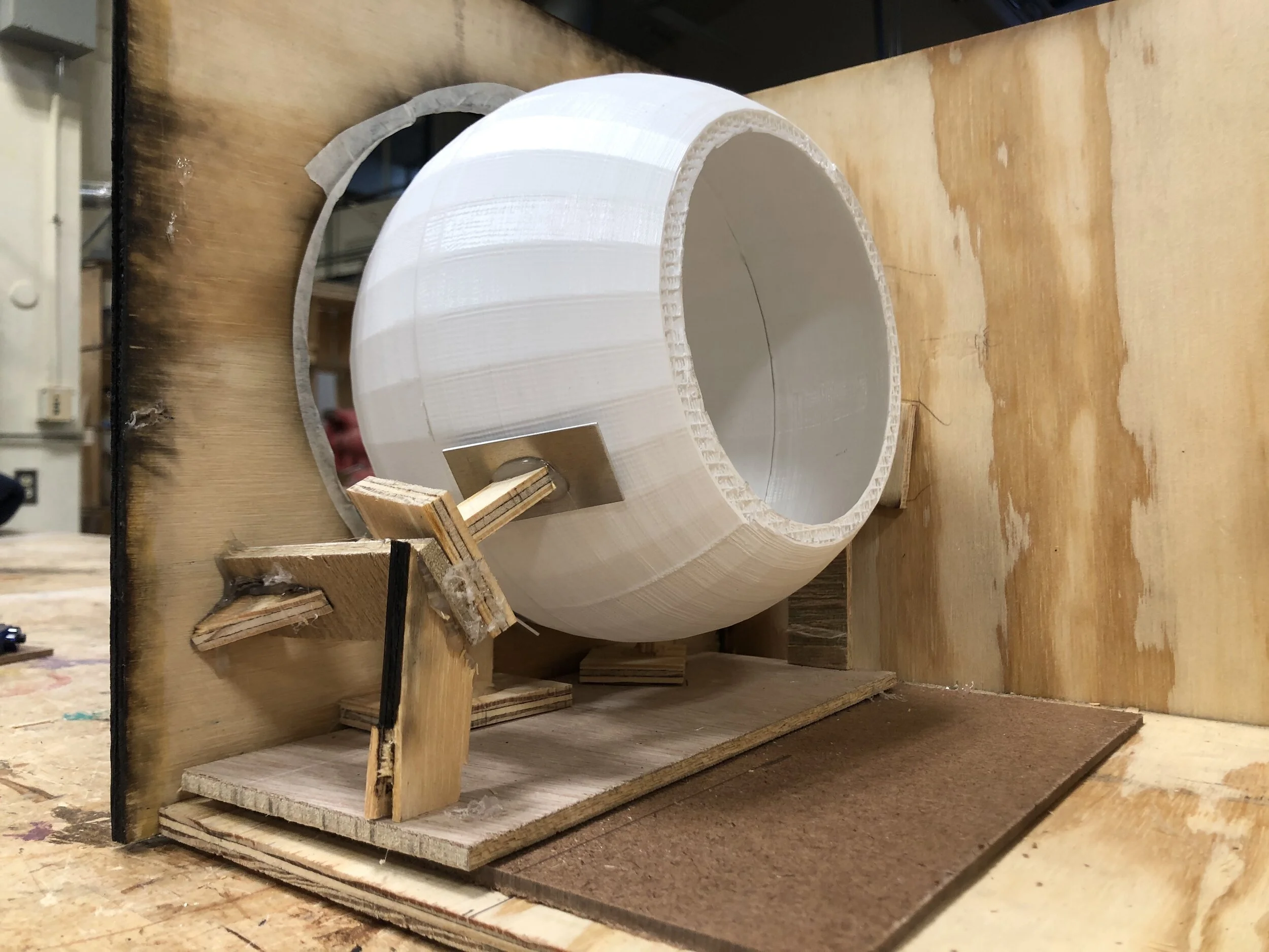
Version 2: Internal Support Structure, planned, less friction and less dislocation, but did slightly restricted motion.

Internal Support Structure
Kinematics: The eyeball had a range of motion of a 45 degree cone. The large horns attached to the motors had the same length as the diameter of the eyeball, so angular movement of the motor matched the angular movement of the eyeball.
Light Trilateration: In order to find the position of a light source relative to the eyeball, we needed at least 3 light sensors. While testing the light sensors to get them working, we found that the values to be varying, but generally consistent. To fix, we added a “dead zone” in the middle of the sensors to clear the slight variation in values and render any ambient light irrelevant.

Prototyping Light Trilateration: Covering sensor with fingers to read value changes
PID Controls: We created separate PID controls for each servo motor, and implemented a movement cap to prevent potentially fatal large movements. Ultimately, we achieved relatively smooth motion and prevented the eyeball from getting stuck. The separate servo motors worked well with the trilateration because the position was represented by x and y values.
Conclusions & Takeaways
For a short term project this can be considered a success. We ran into multiple problems both hardware and software, but were able to problem solve on spot to overcome these challenges. In the future, it would be interesting to do a rebuild to make all of our final design decisions more seamless and less "hot-glued." It would also be fun to investigate how this design could work with the other sensor we considered - a microphone which detects audio input so the eye looks toward sound.
(Created in collaboration with Scott Kim)